Article
Using ChatGPT to Build a Pattern Display Circuit Without Writing HDL from Scratch
Introduction
When learning FPGA development, I often hear that FPGA Programming Complete Guide, 2nd Edition is one of the best books to work through, so I bought it and started following it.
My HDL background at the time was minimal. I had only spent one day reading an introductory Verilog book and had learned only the basic syntax.
In this article, I document my notes while working through Section 2-3 of the book, “Displaying a Pattern on a PC Monitor.”
Objective
Synthesize a pattern display circuit on FPGA and output an image through the HDMI interface.
Environment
- FPGA: Xilinx Zybo Z7-20
- OS: WSL2 Ubuntu 20.04
- Development Environment: Vivado ML Edition 2022.1 for Linux
Specification
- Output from the FPGA board HDMI port
- Display 8 colors including white and black
-
VGA resolution (
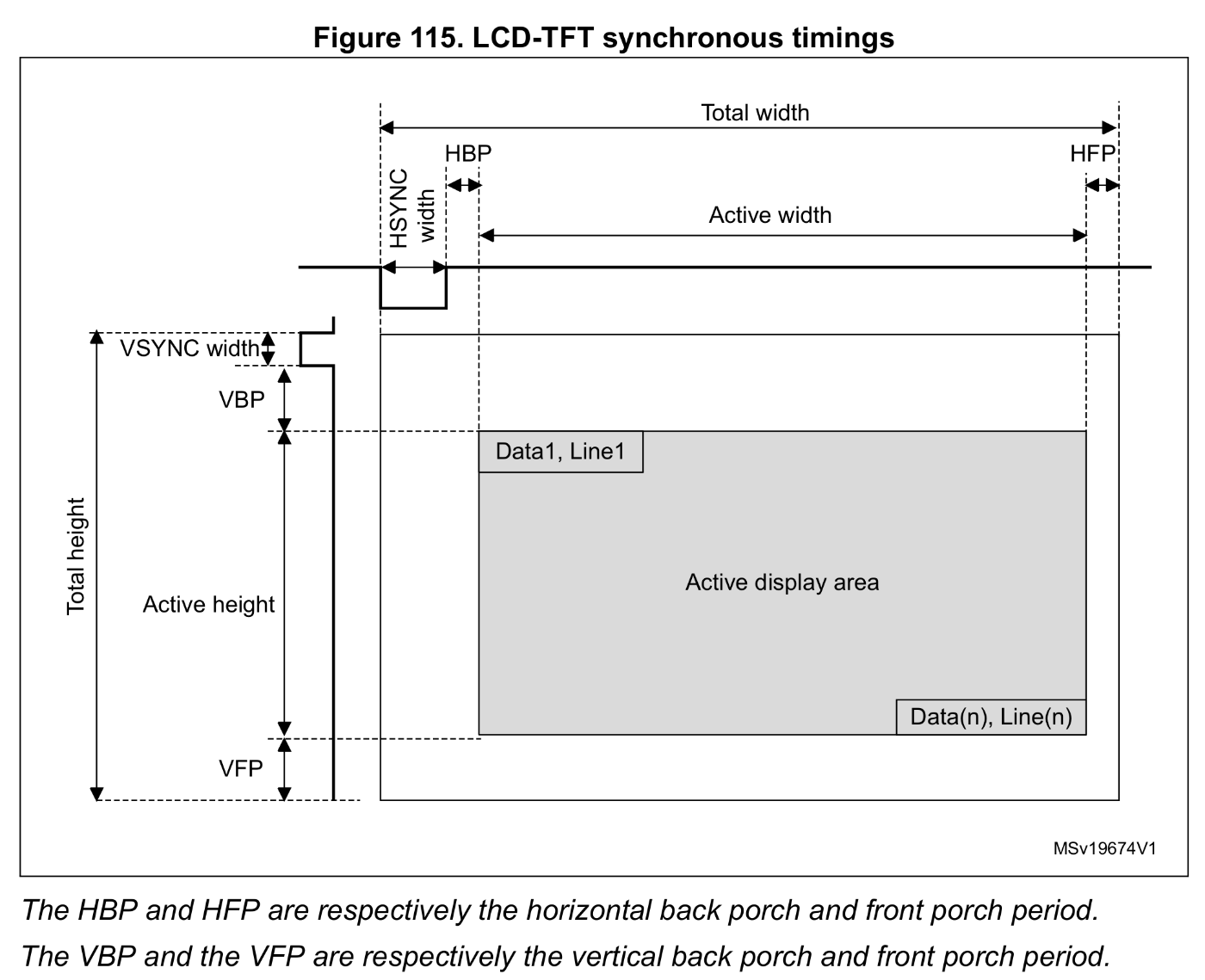
640 x 480) - Timing:
| Pix CLK | H CLK | V CLK |
|---|---|---|
| 25.175 MHz | 31.469 kHz | 59.94 kHz |
| Item | Dot |
|---|---|
| H Period | 800 |
| H Front Porch | 16 |
| H Width | 96 |
| H Back Porch | 48 |
| V Period | 525 |
| V Front Porch | 10 |
| V Width | 2 |
| V Back Porch | 33 |
Pattern Display Circuit
The circuit is composed of the following files:
The code itself is not included here because I was unsure about the copyright status, but it is available at the following URL:
vga_param.vhsyncgen.vpattern.vpckgen.vpattern_hdmi.v
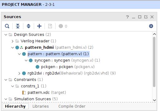
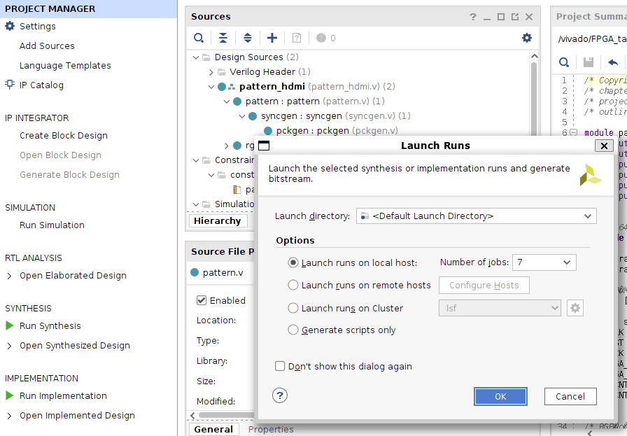
With the project configured as above, simply run Generate Bitstream.
Initial Verification
Capturing the actual HDMI output generated by the FPGA is inconvenient, so I instead used Run Simulation → Behavioral Simulation.
For simulation, I wrote a Verilog test bench that dumps the displayed image through fwrite and added it to the simulation sources, following the method explained in Chapter 3 of the book.
Excerpt:
initial begin
                RST = 0;
    fd = $fopen("imagedata.raw", "wb");
    #(STEP*600) RST = 1;
    #(STEP*20)  RST = 0;
    #(STEP*CLKNUM);
    $fclose(fd);
    $stop;
end

always @(posedge PCK) begin
    if ( VGA_DE ) begin
        $fwrite(fd, "%c", VGA_R);
        $fwrite(fd, "%c", VGA_G);
        $fwrite(fd, "%c", VGA_B);
    end
end
Run SIMULATION → Run ALL to display the waveform.
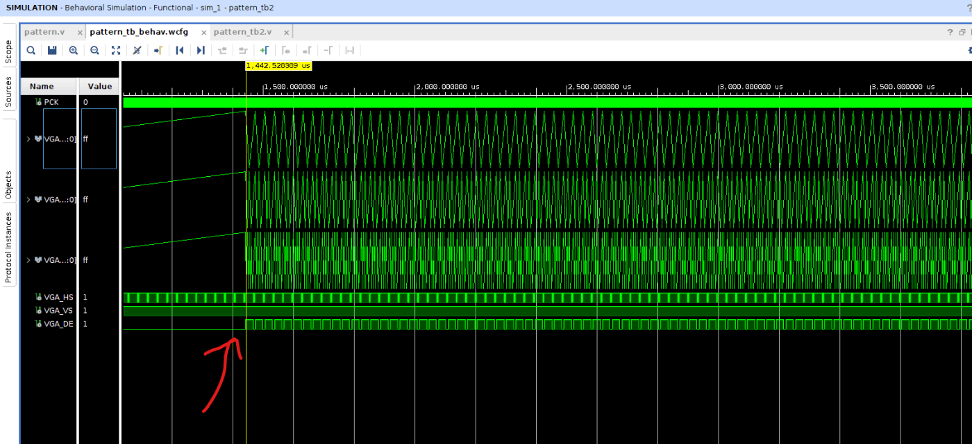
After Data Enable goes high, the R/G/B values begin to change. It is slightly difficult to read because the waveform is shown in analog form.
The image is partly cropped in the screenshot, but one vertical frame corresponds to approximately 1 / 59.94 s, or about 16 ms.
The written RGB data is generated as a raw file under the sim directory in the project root.
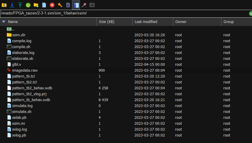
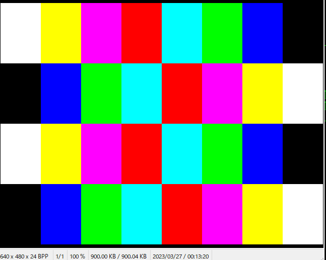
This confirmed that the intended pattern was displayed correctly.
From the top-left corner, the pattern transitions as:
(R,G,B) = White (1,1,1) → Yellow (1,1,0) → Purple (1,0,1) → ... → Black (0,0,0)
Extending the Circuit: Add Gradation and Display a Gradient Pattern
This was the part I wanted to do most. Based on the existing code, I modified pattern.v so that the output image would satisfy the following requirements.
Requirements
- Display a pattern whose gradation changes in 16 levels
- Use 4-bit gradation for each color
- Split the horizontal direction into 10 sections to form 64-dot blocks, and split the vertical direction into 4 sections colored white, red, green, and blue from top to bottom
- Change the gradation every 4 dots in the horizontal direction
Target Image
First, here is the goal image. The final pattern.v should reproduce this pattern:
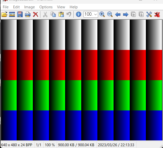
So I discussed it with ChatGPT and used that to build the implementation, because I could not write the HDL comfortably by myself.
module pattern(
    input               CLK,
    input               RST,
    output  reg [7:0]   VGA_R, VGA_G, VGA_B,
    output              VGA_HS, VGA_VS,
    output  reg         VGA_DE,
    output              PCK
);

`include "vga_param.vh"

localparam HSIZE = 10'd80;
localparam VSIZE = 10'd120;
localparam HBLK_SIZE = 10'd64;
localparam VBLK_SIZE = 10'd480 / 4;

wire    [9:0]   HCNT, VCNT;

syncgen syncgen(
    .CLK    (CLK),
    .RST    (RST),
    .PCK    (PCK),
    .VGA_HS (VGA_HS),
    .VGA_VS (VGA_VS),
    .HCNT   (HCNT),
    .VCNT   (VCNT)
);

wire [9:0] HBLANK = HFRONT + HWIDTH + HBACK;
wire [9:0] VBLANK = VFRONT + VWIDTH + VBACK;

wire disp_enable = (VBLANK <= VCNT)
                && (HBLANK-10'd1 <= HCNT) && (HCNT < HPERIOD-10'd1);

wire [3:0] gradient_index = ((HCNT - HBLANK) % HBLK_SIZE) / 10'd4;
wire [1:0] block_index = (HCNT - HBLANK) / HBLK_SIZE;

reg [2:0] color;
always @( posedge PCK ) begin
    case (VCNT / VBLK_SIZE)
        2'd0: color <= 3'b111; // white
        2'd1: color <= 3'b100; // red
        2'd2: color <= 3'b010; // green
        2'd3: color <= 3'b001; // blue
        default: color <= 3'b000;
    endcase
end

reg [3:0] color_level;
always @( posedge PCK ) begin
    if (block_index[0] == 1'b0) begin
        color_level <= gradient_index;
    end else begin
        color_level <= 4'd15 - gradient_index;
    end
end

wire [7:0] VGA_R_temp = color[2] ? color_level * 8'h11 : 8'h00;
wire [7:0] VGA_G_temp = color[1] ? color_level * 8'h11 : 8'h00;
wire [7:0] VGA_B_temp = color[0] ? color_level * 8'h11 : 8'h00;

always @( posedge PCK ) begin
    if ( RST )
        {VGA_R, VGA_G, VGA_B} <= 24'h0;
    else if ( disp_enable )
        {VGA_R, VGA_G, VGA_B} <= {VGA_R_temp, VGA_G_temp, VGA_B_temp};
    else
        {VGA_R, VGA_G, VGA_B} <= 24'h0;
end

always @( posedge PCK ) begin
    if ( RST )
        VGA_DE <= 1'b0;
    else
        VGA_DE <= disp_enable;
end

endmodule
After modifying pattern.v, I ran Generate Bitstream, performed Behavioral Simulation, dumped the raw data, and checked the result as before.
Waveform Check
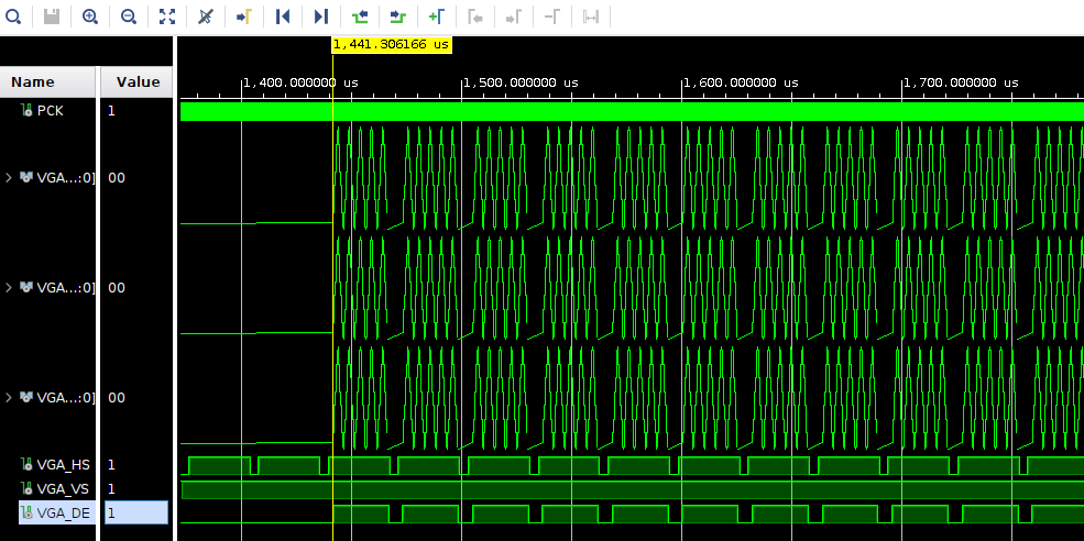
The RGB waveform changes after VGA_DE (Data Enable) goes high.
Displayed Image
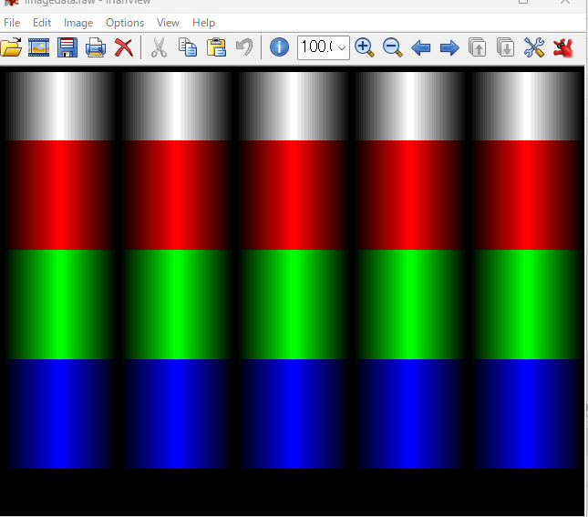
The result is close to the target image, but not fully correct. Since I left most of the logic generation to ChatGPT, that is not too surprising.
The problems were:
- The gradient direction was flipped every 64 dots
- The lower 10% of the screen was completely black, probably because the vertical blanking period had not been handled properly
Then I revised the code:
module pattern(
    input               CLK,
    input               RST,
    output  reg [7:0]   VGA_R, VGA_G, VGA_B,
    output              VGA_HS, VGA_VS,
    output  reg         VGA_DE,
    output              PCK
);

`include "vga_param.vh"

localparam HSIZE = 10'd80;
localparam VSIZE = 10'd120;
localparam HBLK_SIZE = 10'd64;
localparam VBLK_SIZE = (10'd480 - 10'd45 )/ 4;

wire    [9:0]   HCNT, VCNT;

syncgen syncgen(
    .CLK    (CLK),
    .RST    (RST),
    .PCK    (PCK),
    .VGA_HS (VGA_HS),
    .VGA_VS (VGA_VS),
    .HCNT   (HCNT),
    .VCNT   (VCNT)
);

wire [9:0] HBLANK = HFRONT + HWIDTH + HBACK;
wire [9:0] VBLANK = VFRONT + VWIDTH + VBACK;

wire disp_enable = (VBLANK <= VCNT)
                && (HBLANK-10'd1 <= HCNT) && (HCNT < HPERIOD-10'd1);

wire [3:0] gradient_index = ((HCNT - HBLANK) % HBLK_SIZE) / 10'd4;
wire [1:0] block_index = (HCNT - HBLANK) / HBLK_SIZE;

reg [2:0] color;
always @( posedge PCK ) begin
    case ((VCNT - VBLANK + 10'd1) / VSIZE)
        2'd0: color <= 3'b111; // white
        2'd1: color <= 3'b100; // red
        2'd2: color <= 3'b010; // green
        2'd3: color <= 3'b001; // blue
        default: color <= 3'b000;
    endcase
end

reg [3:0] color_level;
always @( posedge PCK ) begin
    color_level <= gradient_index;
end


wire [7:0] VGA_R_temp = color[2] ? color_level * 8'h11 : 8'h00;
wire [7:0] VGA_G_temp = color[1] ? color_level * 8'h11 : 8'h00;
wire [7:0] VGA_B_temp = color[0] ? color_level * 8'h11 : 8'h00;

always @( posedge PCK ) begin
    if ( RST )
        {VGA_R, VGA_G, VGA_B} <= 24'h0;
    else if ( disp_enable )
        {VGA_R, VGA_G, VGA_B} <= {VGA_R_temp, VGA_G_temp, VGA_B_temp};
    else
        {VGA_R, VGA_G, VGA_B} <= 24'h0;
end

always @( posedge PCK ) begin
    if ( RST )
        VGA_DE <= 1'b0;
    else
        VGA_DE <= disp_enable;
end

endmodule
Improved Image
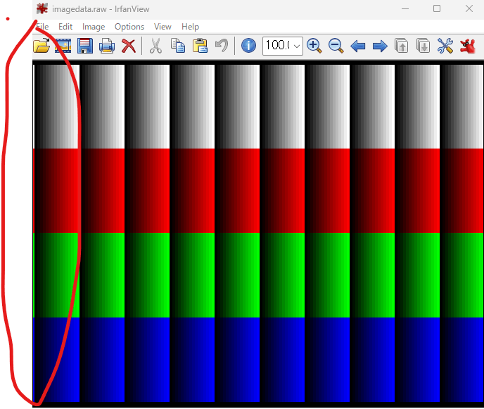
This was much closer to the ideal output, but it still seemed that the far-left gradient started at (R,G,B) = (255,255,255) instead of (0,0,0). Most likely the gradient index calculation was still slightly misaligned.
At that point, only a small offset fix remained. I added +4 so that the modulo result at the far-left edge would shift by one increment:
wire [3:0] gradient_index = ((HCNT - HBLANK +10'd4) % HBLK_SIZE) / 10'd4;
Done.
Conclusion
- Even if you cannot write HDL confidently, combining a clear set of requirements with ChatGPT can still get you surprisingly far.
- My guess is that the final four-line gradient misalignment was caused by the flip-flop stage at the end of the pattern display circuit. That means the horizontal-direction value had to be prepared one clock earlier.