Article
Creating a Bit-Block Display Circuit with Vitis HLS High-Level Synthesis
Introduction
Continuing from the previous post, this article documents the implementation of the “High-Level Synthesis Applications” section from FPGA Programming Complete Guide, 2nd Edition.
In this post, I focus on building a bit-block display circuit with Vitis HLS and treating the result as a reusable IP block.
Environment
- FPGA: Xilinx Zybo Z7-20
- OS: WSL2 Ubuntu 20.04
- Development Environment: Vivado ML Edition 2022.1 for Linux
Objective
Use Vitis HLS to create a bit-block display circuit through high-level synthesis, package it as IP, and combine it with the previously created pattern display circuit inside a Zynq block design for hardware verification.
Previous post: Creating a Pattern Display Circuit with Vitis HLS High-Level Synthesis
Bit-Block Drawing Circuit Specification
- Two source images can be prepared as input.
- Pixel-wise arithmetic is performed between the two images using transparency value
alpha. - The calculation result is stored in display memory.
Implementation
Project Creation to Synthesis
Source code used in this flow is available from the publisher support page:
Main steps:
- Add the source file and test bench.
- Apply HLS directives.
- Run C synthesis.
Below is the source after applying directives:
#include <ap_int.h>
#include "bitblt.h"


u32 calc(u32 src, u32 dst, u8 alpha)
{

    u32 src_r = (src>>16) & 0xff;
    u32 src_g = (src>> 8) & 0xff;
    u32 src_b =  src      & 0xff;

    u32 dst_r = (dst>>16) & 0xff;
    u32 dst_g = (dst>> 8) & 0xff;
    u32 dst_b =  dst      & 0xff;

    dst_r = (alpha*src_r + (255-alpha)*dst_r)/255;
    dst_g = (alpha*src_g + (255-alpha)*dst_g)/255;
    dst_b = (alpha*src_b + (255-alpha)*dst_b)/255;

    return ((dst_r<<16) & 0xff0000) | ((dst_g<<8) & 0xff00) | (dst_b & 0xff);
}

void bitblt(
    volatile u32 *srcin,
    volatile u32 *dstin,
    volatile u32 *dstout,
    u8  alpha,
    u11 width,
    u11 height)
{
#pragma HLS INTERFACE mode=s_axilite port=height
#pragma HLS INTERFACE mode=s_axilite port=width
#pragma HLS INTERFACE mode=s_axilite port=alpha
#pragma HLS INTERFACE mode=m_axi bundle=dst depth=307200 max_write_burst_length=32 num_write_outstanding=16 port=dstout offset=slave
#pragma HLS INTERFACE mode=m_axi bundle=dst depth=307200 max_write_burst_length=32 num_write_outstanding=16 port=dstin offset=slave
#pragma HLS INTERFACE mode=m_axi bundle=src depth=307200 max_read_burst_length=32 num_read_outstanding=16 port=srcin offset=slave
    u32 src[XSIZE], dst[XSIZE];

    height_loop: for (int y=0; y<height; y++) {
#pragma HLS LOOP_TRIPCOUNT avg=240 max=480 min=1
#pragma HLS DATAFLOW
        src_loop: for (int x=0; x<width; x++) {
#pragma HLS PIPELINE
#pragma HLS LOOP_TRIPCOUNT avg=320 max=640 min=1

            src[x] = srcin[x + y*XSIZE];
        }
        dstin_loop: for (int x=0; x<width; x++) {
#pragma HLS PIPELINE
#pragma HLS LOOP_TRIPCOUNT avg=320 max=640 min=1

            dst[x] = dstin[x + y*XSIZE];
        }
        dstout_loop: for (int x=0; x<width; x++) {
#pragma HLS PIPELINE
#pragma HLS LOOP_TRIPCOUNT avg=320 max=640 min=1
            dstout[x + y*XSIZE] = calc(src[x], dst[x], alpha);
        }
    }
}
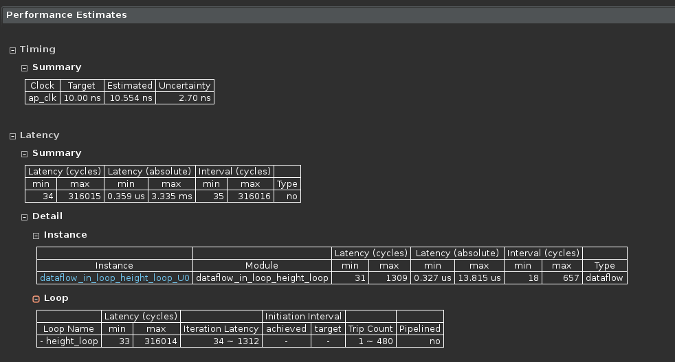
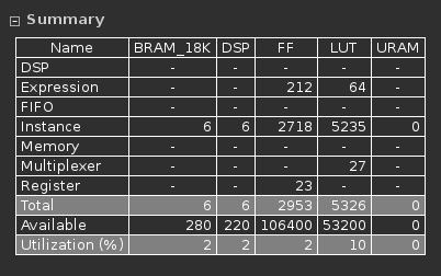
Synthesis Results
- Operating frequency and cycle information:
- Resource usage:
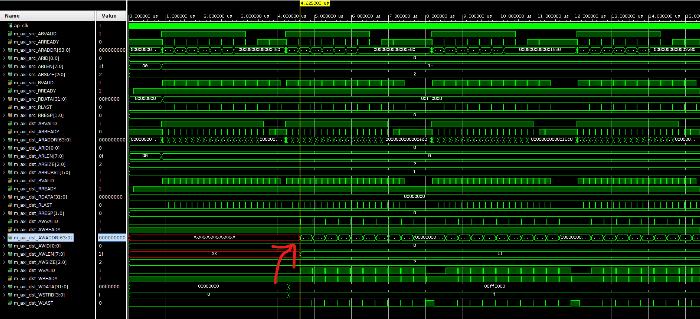
C-RTL Cosimulation
- Run C-RTL cosimulation.
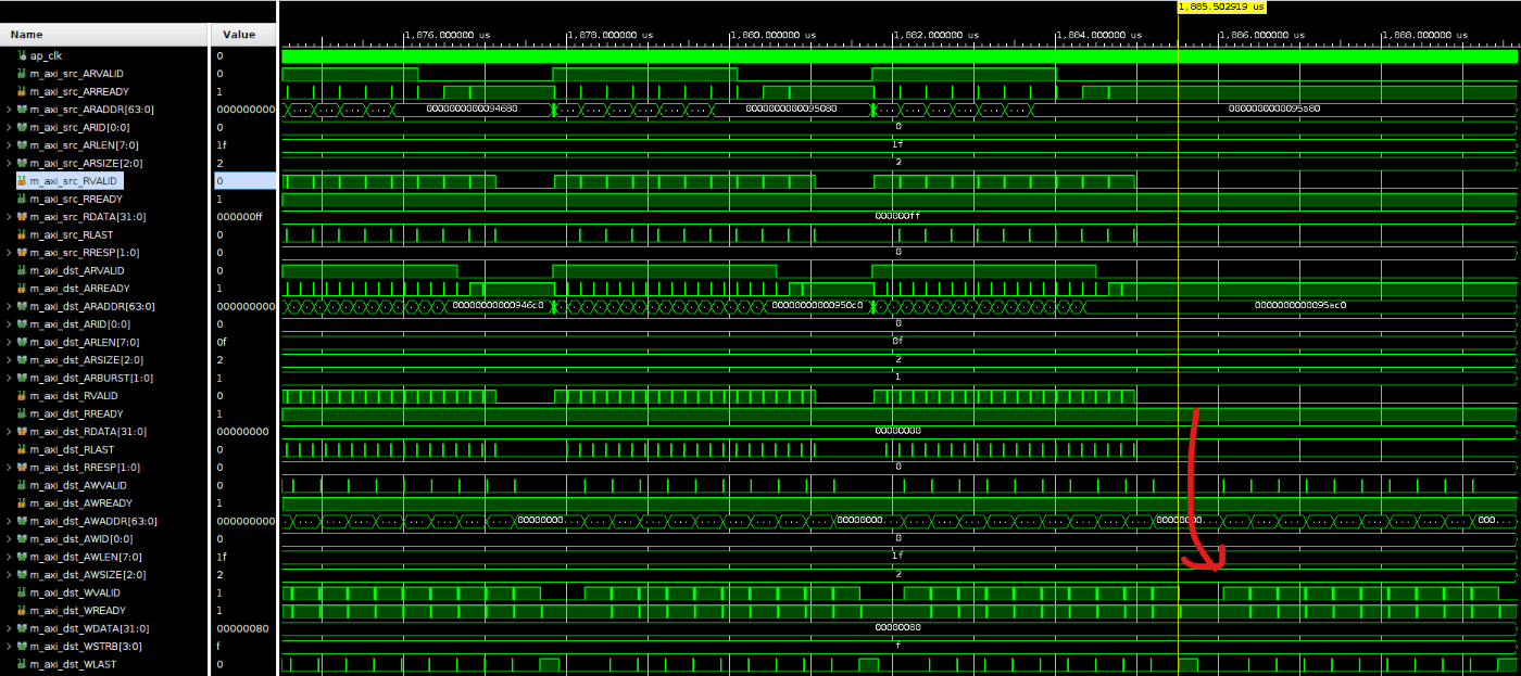
- On the first line, one read port is used for
srcand one read port is used fordst, while no write is yet issued todst.
Single-pixel transaction behavior:
srcport read: burst length = 32, and with 320 pixels per horizontal line, this results in320 / 32 = 10transactions.dstport read: burst length = 16, and with 320 pixels per horizontal line, this results in320 / 16 = 20transactions.- After the transactions complete,
R/AR Validfalls low and leaves margin before the next vertical line begins.
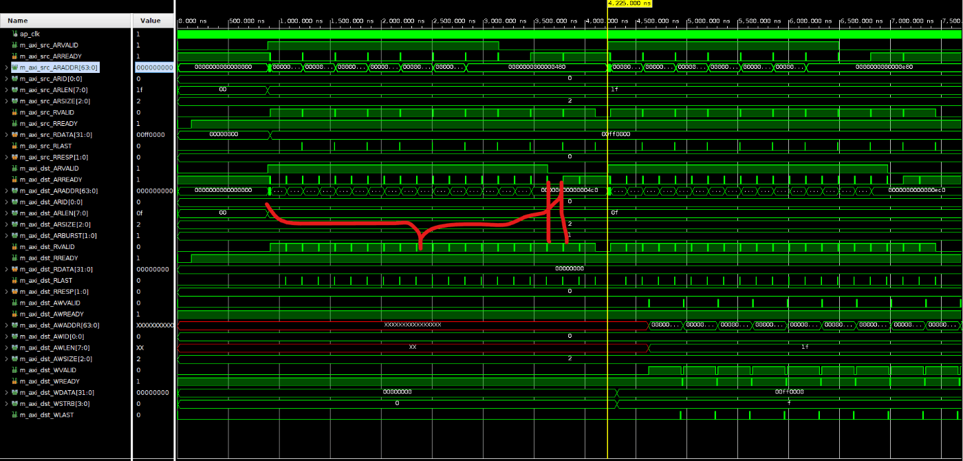
- At the tail end of the pixel processing region, only the write operation on the
dstport remains active. From this, it is clear that pipeline processing has been implemented.
Output Verification
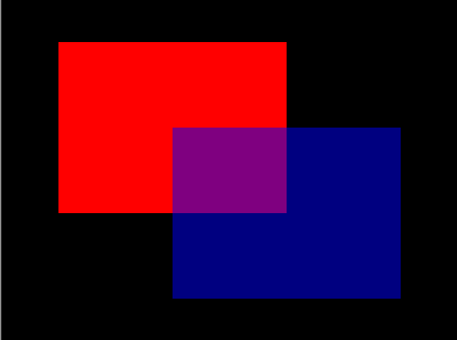
Check the raw file generated by the test bench.
- The center region becomes blue + red, confirming that pixel blending is working correctly.
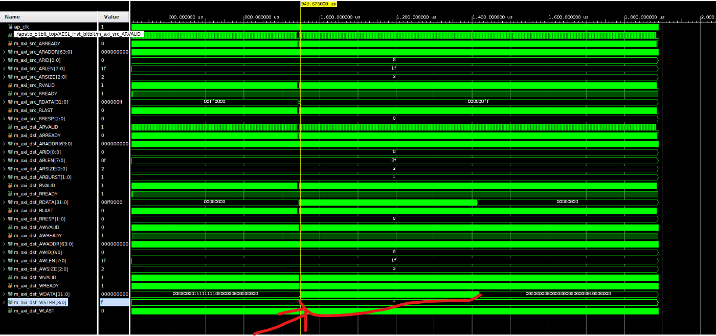
- In terms of data, the relevant region appears as follows:
Final Step
After confirming the result, finish the flow by exporting the RTL and packaging it as IP.