Article
Building a Camera ISP-DPU IP Pipeline from Scratch with AMD FPGA
Introduction
This project builds an end-to-end camera and AI pipeline on a Zynq UltraScale+ MPSoC. Images captured by the Sony IMX219 image sensor are received through MIPI CSI-2, processed by a custom ISP pipeline in the programmable logic, passed to a DPU IP for inference, and displayed on a monitor.
The project starts from AMD-Xilinx’s Kria Smart Camera reference design. It provides a well-integrated baseline for camera capture, image processing, display output, and DPU inference.
However, the reference flow is designed primarily for ease of demonstration. Its application environment depends on Docker running on Ubuntu, while the prepackaged software and hardware stack offers limited flexibility for application-specific customization.
With deployment in a practical embedded application in mind, this project focuses on the following areas:
- an Arm-based heterogeneous architecture combining FreeRTOS on the Cortex-R5F with Docker-free Ubuntu on the Cortex-A53;
- direct DPU execution using the Vitis AI Library and OpenCL;
- the development of a custom FPGA ISP pipeline with Vitis High-Level Synthesis (HLS).
Reference:
The reference application runs its user-space vision stack in a Docker container on Ubuntu on the Cortex-A53 cores. I first reproduced that reference pipeline and confirmed the IMX219 camera, ISP, DPU, and display path. I then extracted the required Ubuntu/Debian user space from the SmartCam Docker image and turned it into a dedicated SmartCam root filesystem. The same baseline pipeline now runs from this rootfs without a Docker runtime.
With the no-Docker baseline established, this project extends the architecture by adding a Cortex-R5F real-time domain, communication between Linux and the R5F through RPMsg, and a custom ISP pipeline implemented in the FPGA fabric. The long-term goal is to add anomaly detection with explicit and measurable real-time guarantees instead of treating the complete vision application as a best-effort Linux workload.
This article is a work in progress. The reference pipeline and its no-Docker migration form the current baseline. The custom ISP, R5F integration, RPMsg protocol, and real-time measurements will be added as the design develops.
Environment
Host PC
- Environment: WSL2
- CPU: AMD Ryzen 9 PRO 7940HS
- RAM: 64 GB (48 GB allocated to WSL2)
- OS: Ubuntu 22.04 LTS
AMD Kria KV260 (Zynq UltraScale+ MPSoC)
- A53 Core: Quad-core Arm Cortex-A53 running Ubuntu 22.04 LTS
- R5F Core: Dual-core Arm Cortex-R5F running FreeRTOS
Tools
- AMD Vivado: 2024.2
- AMD Vitis: 2024.2
Architecture
The system is divided into three execution domains: programmable logic for streaming image processing and AI acceleration, the Cortex-A53 application domain for Linux and application software, and the Cortex-R5F real-time domain for deterministic supervision.
Original Pipeline

Cortex-A53 / Cortex-R5F Pipeline
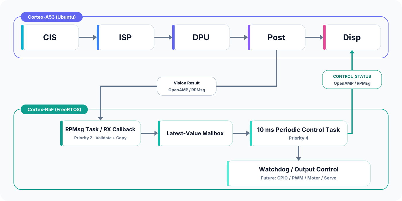
The camera and inference pipeline requires the Vitis AI Library to execute the DPU. Porting this complete software stack to FreeRTOS would require substantial additional implementation work. This design therefore keeps the camera, ISP, DPU, and post-processing pipeline on Ubuntu running on the Cortex-A53 and accepts a limited amount of timing jitter in that domain.
Instead of attempting to make the complete vision pipeline deterministic, the system guarantees real-time behavior in the downstream control path on the Cortex-R5F. The R5F receives the latest vision result through OpenAMP/RPMsg, checks its freshness and deadline, discards stale frames or results, and performs the required GPIO or actuator control within a defined control period. This architecture separates the best-effort camera and AI workload from the deadline-sensitive monitoring and control functions.
Relationship to the Kria SmartCam Reference Design
The AMD-Xilinx reference design provides a useful baseline for the camera platform and DPU integration. Its Sony IMX219 camera path contains the MIPI CSI-2 receiver, an isp_single custom IP, a Video Processing Subsystem, and a frame-buffer writer. The documented test configuration captures 1920x1080 RAW10 data from the IMX219 and displays a 1920x1080 NV12 stream at 30 frames per second. The tutorial then inserts the DPU accelerator used by the SmartCam application.
I reproduced this flow first and used it to verify the complete path before changing the software architecture. This separated camera, ISP, device-tree, and DPU integration problems from issues introduced by the later no-Docker migration.
Baseline PL Capture and ISP Pipeline
The following Vivado block design shows the Sony IMX219 camera pipeline used for the initial baseline.
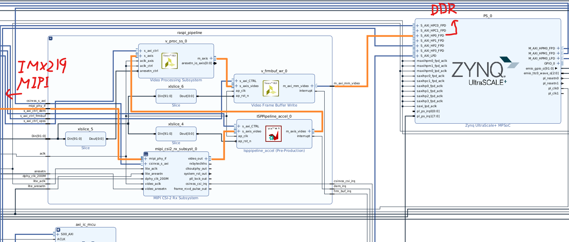
The implemented pipeline consists of the following components:
- IMX219 Image Sensor: Captures incoming light, converts it into RAW Bayer image data, and transmits the data over MIPI CSI-2.
- MIPI CSI-2 Receiver Subsystem (
mipi_csi2_rx_subsyst_0): Decodes the MIPI CSI-2 packets received from the IMX219 and converts the RAW Bayer video into AXI4-Stream Video. - ISP Pipeline (
ISPPipeline_accel_0): A custom IP that applies ISP operations such as demosaicing to the RAW Bayer image and converts it into an RGB-based video stream. - Video Processing Subsystem / VPSS (
v_proc_ss_0): Scales the ISP output to the required resolution. Depending on the configured input and output formats, it can also perform color-space conversion. - Video Frame Buffer Write (
v_frmbuf_wr_0): Converts the AXI4-Stream video from the VPSS into AXI4 memory-mapped write transactions. It writes frames in a configured format, such as NV12, into V4L2 DMA buffers in DDR memory. - Zynq MPSoC
S_AXI_HP0_FPD: Provides the high-performance path that carries the AXI memory-write transactions generated byv_frmbuf_wr_0from the PL into the PS memory system. - PS DDR Controller / KV260 LPDDR4: Stores the completed video frames. Linux applications access these V4L2 MMAP buffers through
/dev/video0.
The complete data path is:
IMX219
  │ MIPI CSI-2 / RAW Bayer
  ▼
MIPI CSI-2 Receiver Subsystem
  │ AXI4-Stream / RAW Bayer
  ▼
ISP Pipeline
  │ AXI4-Stream / Processed Video
  ▼
Video Processing Subsystem
  │ AXI4-Stream / Scaled Video
  ▼
Video Frame Buffer Write
  │ AXI4 Memory-Mapped Write
  ▼
S_AXI_HP0_FPD
  ▼
V4L2 DMA Buffer in DDR
  ▼
/dev/video0
The blue AXI connections in the block design provide register control for the CSI-2 receiver, ISP, Video Processing Subsystem, and frame-buffer writer. The interrupt signals report frame, CSI-2, ISP, and frame-buffer events to the processing system.
This memory-backed baseline is straightforward to validate and matches the reference software flow. It also makes DDR bandwidth and buffer ownership important design constraints. Later measurements will determine whether the custom ISP and DPU path should retain this frame-buffer boundary or use a more direct streaming connection for part of the inference path.
Docker-Free SmartCam Root Filesystem
The reference application packages its camera, display, and DPU user space in Docker. After verifying that pipeline, I extracted its approximately 1.6 GB Ubuntu/Debian filesystem and used it as a standalone SmartCam rootfs. This preserves the known-good GStreamer/VVAS, Vitis AI 2.5, XRT 2.13, configuration, firmware, and accelerator files without requiring Docker at runtime.
The host Ubuntu system continues to own the Linux kernel, FPGA drivers, physical devices, and xmutil. It loads the FPGA application, bind-mounts /dev, /sys, /proc, and /run into the rootfs, and then launches the GStreamer/VVAS application from that environment. Compatibility between the host drivers, loaded xclbin, device nodes, and rootfs libraries is therefore treated as one reproducible software baseline.
Removing Docker does not make the Cortex-A53 workload real-time. It simply provides a controlled application environment with direct access to hardware and RPMsg, while the Cortex-R5F handles the deadline-sensitive monitoring and control path.
Integrating FreeRTOS into the Original Pipeline
The integration of FreeRTOS on the Cortex-R5F into the existing Cortex-A53 Ubuntu camera-DPU pipeline is described in the following article:
RPMsg Communication
OpenAMP/RPMsg provides the control and telemetry channel between the A53 and R5F. Large image frames should stay in the PL/DDR video path; RPMsg is used for small messages rather than bulk video transfer.
The initial message protocol will include:
| Message | Direction | Purpose |
|---|---|---|
CONFIG |
A53 to R5F | Configure deadlines, thresholds, and operating mode |
FRAME_START |
A53/PL to R5F | Report a frame sequence number and capture timestamp |
INFERENCE_DONE |
A53 to R5F | Report completion time, result status, and confidence |
HEARTBEAT |
A53 to R5F | Prove that the Linux application is responsive |
ANOMALY_EVENT |
R5F to A53 | Report a detected anomaly or deadline violation |
RECOVERY_REQUEST |
R5F to A53 | Request restart, reset, or degraded operation |
STATUS |
Bidirectional | Exchange counters, version information, and health state |
Every message should have a protocol version, message type, payload length, sequence number, timestamp, and integrity check. The protocol must define behavior for queue overflow, R5F reboot, Linux restart, duplicate messages, and incompatible protocol versions.
Real-Time Anomaly Detection
“Real-time” must be expressed as a measurable deadline rather than a general performance goal. The design will define at least the following quantities:
- maximum camera-to-ISP latency;
- maximum camera-to-DPU-result latency;
- maximum jitter for periodic frames;
- maximum time to detect a missing heartbeat or inference result;
- maximum time from anomaly detection to the configured response;
- acceptable frame-drop and deadline-miss rates.
The R5F will supervise these deadlines and maintain counters for late, missing, and invalid events. The anomaly response may include notifying the A53, marking the current result invalid, resetting an accelerator, switching to a degraded non-AI display path, or asserting an external safety signal. The appropriate response depends on the final system requirements and will be specified before implementation.
This architecture can provide deterministic monitoring and response, but it does not automatically make Linux inference deterministic. A real-time claim will only be made after worst-case execution time, contention, and fault-recovery behavior have been measured under representative load.
Result
Profiling with Thread Monitor
The following timeline shows the execution profile of the hardware ISP pipeline and DPU in the original SmartCam design.
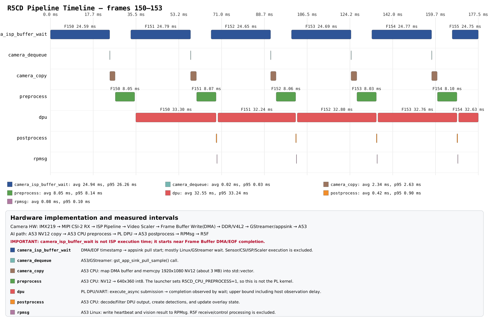
Each hardware-IP interval is measured up to the point at which software observes interrupt completion. Consequently, the measured durations include waiting time inside the Vitis AI Library and should not be interpreted as the pure execution time of the accelerator alone.
This profile indicates clear opportunities to optimize the original SmartCam design. The observed ISP and DPU paths occupy relatively long intervals, while redundant buffer copies introduce additional avoidable overhead. The DPU interval also includes non-maximum suppression (NMS) performed on the software side by the Vitis AI Library, so it represents more than DPU execution alone. This preliminary figure will be replaced with updated measurements that separate accelerator execution, library wait time, memory copies, and software post-processing more clearly.
Zero-Copy Optimization
To remove the redundant camera_copy stage, the optimized pipeline maps the DMA-backed NV12 frame in place. The ISP and frame-buffer hardware write the captured frame into DDR, and the A53 preprocessing stage directly reads the mapped image planes instead of first copying the complete frame into a separate CPU buffer.
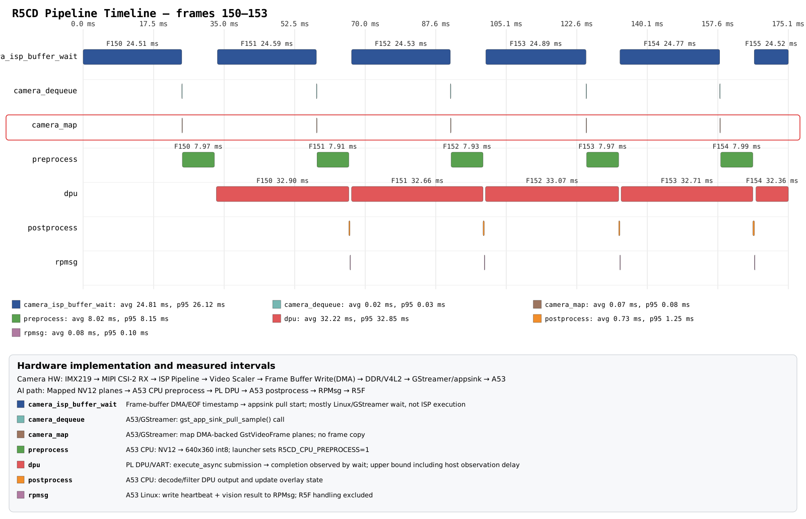
The full-frame camera_copy, which previously took approximately 2.2 ms, is replaced by a camera_map operation of approximately 0.06–0.07 ms. This makes the camera-to-preprocessing handoff zero-copy; preprocessing still generates the model input buffer required by the DPU.