Article
Building a Hardware System with Zynq PS
Introduction
Continuing from the previous post, this article documents the “Hard Macro CPU System” section from FPGA Programming Complete Guide, 2nd Edition.
At this point, my HDL experience was still limited to spending about a day reading an introductory Verilog book and learning only the basic syntax.
Environment
- FPGA: Xilinx Zybo Z7-20
- OS: WSL2 Ubuntu 20.04
- Development Environment: Vivado ML Edition 2022.1 for Linux
Objective
- Control the PL side from the Zynq PS and drive the LEDs
- Use GPIO as input so that the system can be controlled externally
Reference:
Implementation
Hardware Construction
- Create an empty project in Vivado
Create Block Design → Add IPand add the Zynq PS- Add
AXI GPIO, switch it to a 2-channel configuration, and set:- Output →
LED_RGB[2:0] - Input →
BTN[1:0]
- Output →
- Run
Connection Automationso thatSystem ResetandAXI Interconnectare added automatically - Rename the ports to match the constraints file
- Run
Validate Design
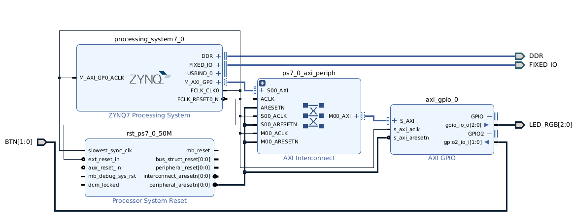
A warning appeared, but the cause was that the skew between the DDR memory and the PS clock had become negative.
Checking the DDR skew settings inside the Zynq PS showed that they matched the negative values mentioned in the warning:

Once the block design is complete, select the design and run Create HDL Wrapper. This generates design_wrapper.v under the design sources.